
Feature
Reinforce a Weak Floor Joist Without Overlooking the Real Problem
By Dale Corrigan · · 24 min read
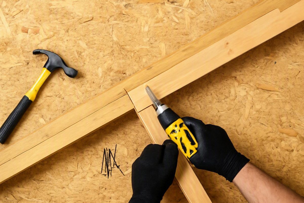
Sistering a floor joist sounds simple: place a new board beside the old one and fasten them together. In practice, the added member must receive load from the floor, share that load through an adequate connection, and deliver it to sound supports. Adding lumber cannot by itself correct active decay, failed bearing, a moving foundation, an inadequate beam, or another break in the load path.
This guide explains how to plan and evaluate sistering repairs for conventional solid-sawn wood floor joists. It does not provide a universal fastening schedule, shoring design, sister length, or authorization to alter structural framing. Those details depend on the building, loads, lumber, damage, supports, and local requirements.
Safety boundary
A homeowner can document visible conditions, map loads and utilities, compare proposed repairs, and verify that completed work matches an accepted detail. Determining structural capacity, suitable sister length, connection strength, required bearing, or a safe lifting method may require a qualified structural professional.
Pause the project and seek professional assessment when damage is extensive, several joists are involved, support conditions are uncertain, settlement appears active, joist ends are badly deteriorated, or significant lifting is proposed.
What Sistering a Floor Joist Actually Does
Sistering means placing a sound framing member directly beside an existing joist and connecting the members so they share load. Depending on the problem and the repair design, the sister may reinforce damaged wood, increase capacity, reduce floor movement, or provide a sounder edge beneath the subfloor.
Three objectives are often confused:
- Strength is the ability to carry the required load without structural failure.
- Stiffness is resistance to bending and vibration under load.
- Levelness describes the floor’s elevation and slope.
These objectives overlap, but they are not interchangeable. A successful sister may make a floor stronger or less bouncy while leaving some historic sag. Conversely, pushing a floor closer to level does not establish that its joists, beams, columns, or foundations are adequate.
Sistering can also be less disruptive than removing an original joist beneath an intact floor. Replacement may disturb subfloor fasteners, finished flooring, plumbing, wiring, blocking, and other framing. Community repair discussions suggest that replacement becomes more practical when the floor and subfloor have already been removed, whereas sistering can preserve an assembly that would be difficult to detach and refasten cleanly. That discussion is practical experience rather than a structural design standard (community comparison of joist replacement and sistering).
This guide is limited to conventional solid-sawn lumber. Do not apply it automatically to:
- Wood I-joists
- Open-web floor trusses
- Metal-plate-connected framing
- Other manufactured or engineered floor systems
Repairs should follow a manufacturer-approved detail or a design prepared for the particular member. General sistering guidance for solid lumber is not a substitute for that information.
Finally, sag, slope, noise, or bounce is a symptom—not proof that one joist has failed. Similar symptoms may arise from a damaged beam, decayed sill, compressed shim, weak column, inadequate footing, moving foundation, poor subfloor attachment, or a combination of conditions. Commercial floor-repair guidance likewise warns that uneven floors can reflect broader structural or moisture problems rather than an isolated joist defect (overview of floor-joist symptoms and related structural problems).
Diagnose the Floor System Before Adding Lumber
Begin with the entire floor assembly. Trace the apparent load path from the finished floor through the subfloor, joists, beams or bearing walls, columns, footings, and foundation. The purpose is not to perform a structural calculation yourself, but to identify what must be inspected or verified before a repair is selected.
Use strong lighting and examine the framing from more than one direction. A joist may appear sound at midspan while being deteriorated where it enters a masonry pocket or rests on a damp sill.
Suggested observation sequence:
- Subfloor: Look for staining, softness, delamination, loose attachment, damaged seams, gaps, and areas that do not appear to contact the joists.
- Joists in the affected area: Compare neighboring members instead of examining only the joist beneath the visible low spot.
- Joist ends: Record apparent rot, crushing, splitting, missing bearing, loose hangers, corrosion, or gaps at supports.
- Blocking and bridging: Note missing, detached, cut, or displaced pieces and joists that appear to have rolled sideways.
- Rim or band joist: Look for decay, separation, insect activity, or poor connections at the perimeter.
- Sill plate: Record visible moisture damage, crushing, gaps, or apparent loss of support.
- Beams and headers: Note cracks, rotation, decay, visible deflection, damaged splices, and concentrated loads that do not appear aligned with support.
- Columns, piers, and shims: Check alignment, visible bearing, corrosion, deterioration, loose wedges, and improvised or displaced supports.
- Foundation and footings: Record visible movement, cracking, settlement, displaced masonry, soft soil, or supports bearing on questionable surfaces.
For each joist, document observable conditions such as:
- Cracks, checks, splits, shakes, or broken fibers
- Soft, damp, darkened, or discolored wood
- Mold-like growth or recurring condensation
- Insect galleries, frass, fine wood debris, or hollow areas
- Crushed, tapered, or visibly unsupported ends
- Large, closely spaced, or awkwardly located holes and notches
- Missing, corroded, loose, or ineffective fasteners
- Twisting, rolling, bowing, or apparent misalignment
- Loss of direct bearing or incomplete hanger engagement
Do not treat “inadequate span,” “insufficient remaining capacity,” or “enough sound wood for a connection” as visual findings. Those are design determinations. Record the dimensions and conditions so they can be checked against approved plans, applicable span information, or professional analysis.
Common contributors identified in the available guidance include plumbing leaks, crawl-space moisture, rot, insects, overloading, excessive notching, poor installation, excessive span, and compromised fasteners. Sagging-floor investigations may also reveal damage to the sill, rim member, main beam, shims, columns, or foundation rather than one isolated joist (commercial overview of floor-system components and sagging-floor causes).
Symptoms above the framing can help map movement but generally cannot identify its cause by themselves. Record gaps below baseboards, sticking doors, drywall cracks, nail pops, floor slope, and whether any symptom is changing. Do not select a repair from one symptom alone.
Correct active water entry, pest activity, and failed support conditions before concealing them.
Pause work and obtain an assessment if you observe:
- Evidence of continuing foundation or support movement
- Widespread decay or insect damage
- A badly crushed, decayed, or apparently unsupported joist end
- A split that substantially separates the member
- Several affected joists
- A moving beam, column, pier, wall, or masonry pocket
- An unknown or questionable support beneath the proposed work
- Uncertainty about what supports either joist end
These conditions do not prove that sistering is impossible. They indicate that the cause, remaining capacity, and support system need to be established before framing is altered. Do not remove structural members, cut utilities, or begin lifting merely to improve access while those questions remain unresolved.
Decide Whether to Sister, Replace, Patch, or Add Support
Sistering may be suitable when a solid-sawn joist is otherwise supportable, the problem is localized or clearly defined, and the new member can be given a viable load path. It is one possible repair—not the default answer to every crack, sag, or squeak.
Use this decision tree to organize the next step.
1. Are the joist’s supports stable and sound?
- No or uncertain: Investigate and address the support system first.
- Yes, based on an accepted assessment: Continue.
2. Is the damage localized, and has the remaining wood been found suitable for the proposed connection?
- Yes: A sister or case-specific localized repair may be possible.
- No or unknown: Replacement or a broader designed repair may be more appropriate.
3. How many joists are affected?
- One or a small localized group: Individual reinforcement may be practical.
- Several sound but overly flexible joists: A properly founded supplemental beam may reduce their effective span more directly.
- Several damaged joists: Investigate a common cause and seek structural review.
4. Can the new member reach sound bearing or an approved end connection?
- Yes: A continuous sister may provide the clearest load path.
- No: Treat the obstruction as a connection-design problem rather than choosing an arbitrary overlap.
5. What is the objective?
- Reinforcement: The joist may be strengthened in its current position.
- Leveling: A separate lifting and temporary-support plan may be needed.
- Both: The lift, alignment, connection, and final support condition must be coordinated.
Replacement may be considered when deterioration is extensive, sound connection material is limited, or the joist ends and surrounding supports require reconstruction. It can also be more practical when the floor assembly has already been removed and the framing is fully accessible. Whether replacement is actually preferable remains a project-specific judgment.
Plywood reinforcement is sometimes proposed for particular splits or localized defects, but it is not a generic substitute for a sister joist. Its thickness, extent, orientation, adhesive, fastening, and relationship to the defect must suit the particular repair.
Where several joists are structurally sound but too flexible for their span or loading, a properly designed supplemental beam may be more direct than sistering every member. The beam still needs a verified route through columns, piers, footings, or other adequate supports.
Possible engineered alternatives include:
- Laminated veneer lumber
- Steel flitch reinforcement
- Sisters on both sides of the original joist
- Custom hangers or end plates
- A new header or transfer connection
- Added support beneath the affected region
- A combination of replacement and reinforcement
Professional review is appropriate for major new loads, including a new bearing wall, substantial remodeling, a large tub, stone finishes, or other concentrated loads. It is also appropriate for extensive decay, multiple damaged joists, active settlement, uncertain bearing, engineered framing, complicated partial sisters, or significant lifting.
Record the Joist, Load, and Access Conditions
Before buying lumber or fasteners, create a worksheet for each affected joist. Measuring only the visible defect is not enough.
| Item | Record |
|---|---|
| Joist depth and actual thickness | Measure the existing member rather than relying on nominal size |
| Clear span | Measure between the faces of the actual supports |
| Joist spacing | Record center-to-center spacing |
| Species or grade marks | Photograph every visible stamp or mark |
| Damage | Note type, length, depth, direction, and distance from each support |
| End support | Identify the visible wall, beam, hanger, ledger, header, or masonry pocket |
| Bearing condition | Record contact, gaps, crushing, decay, and hanger engagement |
| Number affected | Include neighboring joists with related symptoms |
| Floor condition | Record slope, low points, bounce, noise, and visible movement |
| Moisture evidence | Note active leaks, staining, dampness, condensation, and soil moisture |
| Proposed objective | Reinforcement, reduced bounce, leveling, or a combination |
Map loads above the repair. Mark walls, tubs, stone surfaces, cabinets, islands, fireplaces, heavy appliances, storage areas, and proposed remodeling. Record whether walls run parallel or perpendicular to the joists, but do not decide from orientation alone whether a wall is load-bearing. That may require examining the framing above and below or reviewing approved plans.
Map every obstruction:
- Supply, drain, waste, and vent piping
- Electrical cables, boxes, and conduit
- Heating and cooling ducts
- Gas and other mechanical lines
- Blocking, bridging, and strongbacks
- Masonry pockets and foundation projections
- Stair openings, headers, and trimmers
- Existing holes, notches, patches, and hardware
- Areas concealed by ceilings, built-ins, or insulation
A straight, sound sister comparable in depth to the existing solid-sawn joist is a common proposal, but the exact material, species, grade, size, and stiffness are design decisions.
Also plan for:
- Safe access and a stable work platform
- Suitable lighting and ventilation
- Eye, hearing, respiratory, hand, and head protection for the work
- A tape, level, straightedge, string line, and moisture meter
- Clamps suitable for drawing accessible faces together
- Help handling long or heavy members
- Temporary-support equipment only when specified
- The exact structural fasteners and connectors named in the repair detail
- Compatible drivers, drills, bits, or installation tools
- Adhesive only if the accepted detail requires it
- Restoration of blocking, utility protection, and access finishes
Do not drill or notch a proposed sister merely to reproduce penetrations in the original joist. Existing openings may themselves be part of the problem, and new cuts can remove the wood intended to provide reinforcement. Structural and trade requirements must be coordinated before pipes, cables, or ducts are rerouted.
Permit and inspection requirements vary by jurisdiction and scope. General framing provisions do not amount to one universal sistering specification, and deck-oriented guidance should not be treated as a prescriptive interior-floor repair. Ask the local building department whether drawings, a permit, an inspection, or a professional repair detail will be required before purchasing materials (discussion of sistering and variable code or inspection requirements).
Plan the Sister’s Length, Bearing, and Load Path
A continuous sister extending from one support to the other is generally preferred when feasible because it creates an understandable route: floor load enters the sister, travels along it, and is delivered to walls, beams, or approved end connections.
Direct bearing is not the only possible support condition. A specified joist hanger, custom connector, header connection, or another designed assembly may transfer the end reaction. But fastening a board only to the side of the original joist does not automatically establish adequate support for the new board.
A partial sister behaves differently. It receives load in the reinforced region and transfers force back into the original joist near its endpoints. The connection and the remaining portions of the original joist must resist those transferred forces. Relevant design checks may include bending, shear, connection capacity, fastener placement, wood condition, and force concentrations near the sister ends. An informal engineering-forum discussion illustrates why partial sisters and their endpoint connections must be evaluated together, but it does not provide a general construction specification (discussion of force transfer in partial-length sisters).
Do not rely on rules such as “overlap one-third of the joist” or “extend at least three feet” as universal interior-floor requirements. Such figures appear in some general or deck-focused material, but the evidence does not establish them as safe for every floor repair. Defect location, span, loading, joist condition, sister stiffness, bearing, and connection capacity all matter.
Utilities frequently determine whether a full-length member is practical. Ducts may fill a joist bay, pipes or cables may cross the sister’s path, masonry pockets may be inaccessible, and stair headers may create different end conditions from ordinary wall bearing.
Planning options include:
- Having utilities relocated by qualified trades
- Using a specified hanger or custom end connection
- Selecting a different reinforcement material or geometry
- Placing reinforcement on the opposite face
- Adding properly supported framing below
- Replacing a deficient header or support
- Obtaining a designed partial-sister detail
The diagram below is conceptual. It is not a construction detail or fastening schedule.
A. Continuous load path

 SUPPORT                                      SUPPORT
   █                                             █
   █=============================================█  existing joist
   █=============================================█  full-length sister
          load can travel to both supports


B. Partial sister

 SUPPORT                                      SUPPORT
   █                                             █
   █=============================================█  existing joist
          |===========================|             partial sister
          ↑                           ↑
       force-transfer zones near the sister ends


C. Attached without verified support

 SUPPORT                                      SUPPORT
   █                                             █
   █=============================================█  existing joist
        |=================================|         sister
        X                                 X
     no verified bearing or designed transfer connection
The central question is not simply how much overlap exists. It is how load from every part of the sister reaches support—and whether the original wood and connections can carry the forces introduced along the way.
General Installation Workflow for a Solid-Sawn Joist
The following sequence is a proposal-evaluation and workmanship checklist, not a standalone repair method. Installation should follow an accepted, project-specific detail that identifies the sister material, extent, connection, bearing, and any temporary support.
Step 1: Expose enough of the floor system.
The work area should reveal the affected joist, its ends, nearby framing, subfloor, blocking, supports, and utilities. A narrow opening around one crack may conceal deteriorated bearing or a broader moisture problem.
Before cutting ceiling material, locate electrical, plumbing, mechanical, and other hazards. Do not assume a joist bay is empty because no utility is visible from one end.
Step 2: Address causes and specified stabilization.
Correct active leakage, moisture entry, pest activity, weak bearing, displaced shims, or failed supports before concealing the area.
If the accepted plan requires temporary support, the plan should identify the supporting beam, jack or post locations, bearing points, base condition, and removal sequence. A generic jack arrangement is not a substitute for a shoring or lifting plan.
Step 3: Remove only necessary blocking or bridging.
Only pieces that prevent access should be removed, and their locations should be recorded so they can be restored. If blocking serves a structural, fire-blocking, or other required function, the plan should address how that function is maintained while the work is open.
Step 4: Dry-fit the proposed sister.
Verify that the member fits the intended route and can reach its required bearing or end connectors. General sistering guidance commonly recommends installing dimensional lumber with its natural crown upward, but the accepted repair detail and actual member geometry should control rather than a universal rule (general sistering workmanship guidance).
Inspect the new member for splits, severe warp, or edge damage. Do not rely on screws or bolts to force severely distorted lumber into alignment.
Step 5: Verify alignment and contact.
The accepted detail should define whether the sister is to contact the subfloor, match the existing joist’s position, or be held at another planned elevation. Clamps may help close accessible gaps, but they should not be used to crush wood or force framing around pipes, cables, or ducts.
Investigate gaps caused by debris, projecting fasteners, irregular framing, or warped lumber instead of hiding them behind hardware.
Step 6: Use adhesive only when specified.
Some repair guidance calls for compatible structural-grade construction adhesive on clean, dry, closely fitted surfaces. Adhesive is supplemental unless a project-specific design states otherwise; it does not replace sound wood, adequate structural fasteners, required sister length, or end support.
Follow the product instructions for substrate preparation, temperature, bead size, open time, clamping, and curing.
Step 7: Install only the specified structural fasteners.
The repair detail should identify the structural nails, screws, bolts, washers, and connectors. Follow the applicable product instructions for:
- Diameter and length
- Number and spacing
- Rows and staggering
- End and edge distances
- Washers and associated hardware
- Pilot-hole requirements
- Tool settings and installation angle
- Corrosion compatibility
- Product limitations
There is no universal schedule for every sistered floor joist. Fastener requirements change with the loads, lumber, damage, sister length, bearing, and transfer mechanism. Community discussion of old joists also illustrates that structural screws, framing nails, adhesive, and pilot holes are treated differently under different conditions; it should not be read as a substitute for a designed schedule (discussion of fasteners and splitting concerns in older joists).
Step 8: Complete the specified end support.
The sister should be seated on its intended bearing or connected through the specified hanger, header connection, plate, or other hardware. Verify connector size, placement, and required fastener installation against the accepted detail and product instructions.
Side fasteners between joists do not replace end support unless the repair was specifically designed to transfer the sister’s reaction back into the original joist.
Step 9: Restore and inspect.
Restore blocking, bridging, and required fire-blocking. Verify subfloor contact where the detail requires it, and check for newly split wood, deformed hardware, projecting fastener heads, or pinched utilities.
Temporary support should be released only in the sequence established by the repair plan.
                 SUBFLOOR
   ─────────────────────────────────────
       contact where the detail requires it

   ╭──────────────────────────────────╮
   │ existing joist                   │
   │  •       •       •       •       │
   │      •       •       •       •   │  conceptual stagger only
   ╰──────────────────────────────────╯
   ╭──────────────────────────────────╮
   │ sister joist                     │
   ╰──────────────────────────────────╯
     █                              █
   end support                  end support

        [blocking restored between joists]
The diagram shows relationships only. It does not prescribe dimensions, spacing, fastener type, or bearing length.
Handle Sag, Jacking, and Utility Conflicts Cautiously
Reinforcement and leveling are separate operations. A joist can be strengthened in its existing position. Correcting established sag may move the joist, subfloor, finishes, walls, cabinets, and utilities resting on or connected to the floor.
Temporary lifting may be used in some repairs to align an old joist with a straight sister or relieve load while a connection is installed. The lifting beam, jack locations, bearing points, support below, target position, and unloading sequence must be planned for the actual structure.
There is no universal safe lift amount, rate, or jack spacing.
Possible consequences include:
- Cracked drywall or plaster
- Separated trim and caulk joints
- Damaged tile, stone, or finished flooring
- Movement of cabinets or countertops
- Binding doors and windows
- Stressed or leaking plumbing
- Taut electrical cables or displaced boxes
- Damaged ducts
- Movement in adjacent joists, walls, beams, or columns
Commercial contractor guidance specifically cautions that floor lifting can damage drywall, paint, flooring, counters, and trim. That warning supports treating leveling as a separate operation rather than an automatic part of sistering (contractor guidance on joist sistering and lifting risks).
If cracking increases, finishes move unexpectedly, plumbing binds or leaks, wiring becomes taut, a support shifts, a jack leans, or neighboring framing moves unexpectedly, stop the operation and have the condition reassessed.
Utility conflicts require the same restraint. Pipes, cables, conduit, and ducts should be relocated correctly or accommodated through a designed alternative. They do not justify an unapproved hole or notch in the sister.
Pilot holes may be appropriate for certain fasteners and conditions, but their size and location should follow the fastener instructions and repair detail. Maintain specified end and edge distances, and do not continue driving fasteners if new splitting develops.
After temporary support is released, a dimensional-lumber sister may improve stiffness without removing all existing sag. Residual shape does not necessarily show that reinforcement failed. Evaluate the completed work against its approved structural and leveling objectives, not an assumption that sistering must produce a perfectly flat floor.
Inspect the Repair and Monitor the Floor
Inspect the work before closing the ceiling or crawl-space access. Use the accepted repair detail, connector instructions, and inspection requirements as the controlling checklist.
Final inspection checklist:
- The sister reaches its intended bearing or specified end connectors.
- Bearing surfaces and connector engagement match the detail.
- Hangers, plates, or custom connectors are correctly positioned.
- Member contact matches the intended configuration.
- Fasteners match the specified products and pattern.
- Heads, washers, and connector fasteners are properly seated.
- No new splitting, crushing, or breakout is visible.
- Blocking and bridging have been restored as required.
- The sister contacts the subfloor where specified.
- Utilities are not pinched, punctured, overstretched, or left unsupported.
- Temporary-support equipment has been removed or retained as directed.
- Required fire-blocking, insulation, and protective plates are restored.
- The work remains visible for any required inspection.
Confirm that the moisture or pest source has been addressed. Examine joist ends, sill areas, beam pockets, and other locations that will become difficult to inspect after closure. Do not conceal visibly soft or deteriorated wood merely because a new board now covers part of the original member.
Every element of the accepted repair matters. Excessive or poorly placed fastening may also split the members.
Photograph the work before covering it. Include:
- Overall views showing sister length
- Both end supports
- Visible lumber markings
- Fastener and connector packaging
- The installed connection pattern
- Restored blocking and bridging
- Corrected moisture or pest conditions
- Utility routes that will later be concealed
Record material sizes, fastener products, connector models, permit information, inspection results, and approved field changes. These records can help future owners and trades avoid hidden hardware and understand the repair.
After the floor returns to normal loading, seek renewed evaluation if you observe:
- Continuing or accelerating movement
- New or expanding cracks
- Fastener or connector movement
- Recurring staining or dampness
- New insect galleries or debris
- Increasing bounce or noise
- Worsening door, wall, or trim symptoms
- Movement at a beam, column, pier, or foundation support
Depending on the jurisdiction and project, an inspector may examine dimensions, alignment, bearing, connections, framing condition, and consistency with approved documents. Inspection does not replace design, but it can verify that required work remains visible and matches what was accepted.
A structurally improved floor may retain historic slope or deflection. The important questions are whether the cause has been controlled, the required load path exists, and movement has stabilized.
Permits, Professional Help, and Realistic Cost Variables
Permit and inspection requirements vary by jurisdiction and project scope. The available evidence does not establish one comprehensive prescriptive code procedure for sistering a damaged interior floor joist. Ask the local building department what it requires before structural work begins, particularly when a repair changes bearing, introduces a beam, alters utilities, or affects several members.
Structural review is advisable for:
- Multiple damaged joists
- Severe or extensive decay
- Crushed or missing end bearing
- Evidence of active settlement
- Major proposed loads
- Engineered I-joists or floor trusses
- Uncertain walls, beams, columns, or foundations
- Partial sisters with complicated load transfer
- Significant floor lifting
- Custom steel, LVL, hanger, or header details
- Any condition in which remaining capacity is uncertain
Different professionals have distinct roles:
- A structural engineer can evaluate the load path and specify the reinforcement, connection, support, and lifting assumptions.
- A building official can explain local permit, submittal, and inspection procedures.
- A framing contractor can plan access and execute an accepted repair.
- An electrician can relocate or protect wiring.
- A plumber can relocate piping and address leaks.
- A mechanical contractor can handle ducts and related equipment.
- A pest or moisture professional can investigate and treat biological or water-related causes within that professional’s scope.
Published prices are not directly comparable. A commercial contractor article published in January 2025 lists floor-joist sistering at $12–$15 per linear foot, but the figure is a company estimate rather than a national average and may depend on region, access, scope, and service model (commercial floor-repair price example).
Other published material estimates work per joist and may focus on deck framing rather than an interior floor. Those figures use different units and may exclude demolition, engineering, support repairs, utilities, permits, and finish restoration. An isolated price should not be treated as a complete budget.
Important cost drivers include:
- Number, depth, and length of affected joists
- Basement, crawl-space, or finished-ceiling access
- Demolition and finish restoration
- Temporary support and lifting
- Utility relocation
- Moisture, drainage, or pest remediation
- Repair of sills, beams, columns, or masonry pockets
- Lumber, LVL, steel, connectors, and fasteners
- Engineering and drawings
- Permit and inspection fees
- Work sequencing in an occupied building
- Restoration of insulation, blocking, and fire protection
When comparing quotes, require each contractor to state:
- Proposed sister material and length
- Whether the sister runs support to support
- Direct-bearing, hanger, header, or partial-transfer method
- Fastener product and complete schedule
- Adhesive product and purpose, if included
- Temporary-support and lifting plan
- Treatment of plumbing, electrical, and duct conflicts
- Correction of the underlying moisture, pest, or support problem
- Responsibility for engineering, permits, and inspections
- Blocking, fire-blocking, and insulation restoration
- Ceiling, flooring, trim, and other finish repairs
- Conditions that could change the price
- Documentation provided before concealment
A lower quote may omit engineering, support repair, utility work, or finishes. A higher quote may include replacement of deteriorated components another contractor assumes are sound. Compare the proposed load path and full scope, not merely the amount of lumber.
Does a sister joist have to run the full length of the original joist?
Not in every designed repair, but a continuous bearing-to-bearing sister is generally preferred because its load path is easier to establish and inspect. If it cannot reach support, it needs either a specified end connection or a designed transfer into the original joist.
A partial sister creates force-transfer zones near its ends. Its required length cannot be determined safely from a generic minimum-overlap or fraction-of-span rule. The defect location, load, remaining joist capacity, sister stiffness, and connection must be evaluated together (partial-sister engineering discussion).
What screws, nails, or bolts should be used to sister a floor joist?
Use the structural nails, structural screws, bolts, washers, and connectors named in the accepted repair detail. The proper product and schedule depend on the loads, lumber, sister length, bearing, and required force transfer.
Follow the fastener or connector manufacturer’s instructions for length, diameter, spacing, rows, edge distances, pilot holes, tools, and installation. Do not substitute drywall screws or unspecified general-purpose screws. Adhesive, when specified, supplements rather than automatically replaces the mechanical connection and end support.
Can I sister a rotten floor joist instead of replacing it?
Sometimes a designed sister can bypass localized deterioration, but the repair must account for the remaining wood, connection, and path to support. The moisture source and active pest conditions should be corrected before the area is concealed.
If deterioration is extensive, reaches the supports, affects adjacent sills or beams, or leaves uncertain connection material, a broader repair or replacement may be necessary. That determination should follow an assessment rather than an assumption that the new sister makes the rotten wood irrelevant.
Should a sagging floor be jacked level before the joist is sistered?
Not automatically. A floor may be reinforced in its current position, while leveling is a separate operation with separate risks. Temporary lifting may assist alignment, but the lifting beam, jack locations, support below, target position, and unloading sequence must be planned for the building.
Lifting can damage finishes, cabinets, plumbing, wiring, and adjacent framing. There is no universal safe lift amount or rate, and substantial correction warrants qualified planning and monitoring (floor-lifting cautions from commercial repair guidance).
Can dimensional lumber be used to sister an I-joist or floor truss?
Not by applying a solid-sawn joist rule of thumb. I-joists and floor trusses are engineered assemblies whose webs, chords, flanges, plates, and connections perform specific functions.
Use a manufacturer-approved repair detail or a design prepared for the particular engineered member. Do not drill, notch, cut plates, or attach dimensional lumber until the applicable detail identifies the materials, extent, blocking, fasteners, and support conditions.
Sistering is a viable repair only when the cause is understood, the remaining framing and supports are suitable for the proposed work, and the new member has a verified load path through adequate length, connections, and bearing. Use this guide to document conditions and evaluate proposals, but obtain local approval or structural design when the project involves partial reinforcement, uncertain supports, substantial lifting, engineered framing, multiple failures, or major loads.