
How to Choose and Inspect a Foundation Waterproofing System
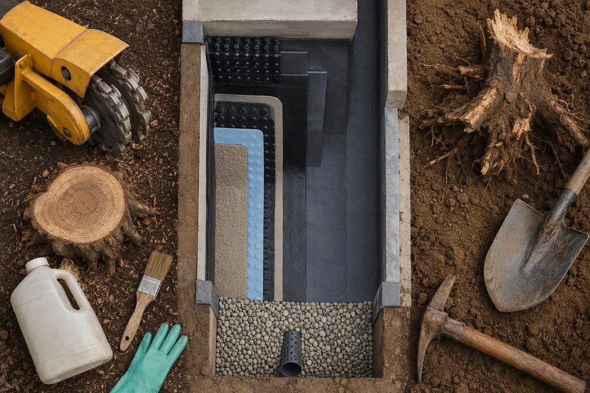
Below-grade waterproofing is easy to misunderstand because the membrane receives most of the attention while the surrounding assembly often determines whether it can work. Water may enter at an untreated joint, pass through a penetration, accumulate because drainage is ineffective, or reach the wall after a collection or discharge system stops functioning.
A reliable selection process therefore starts with exposure rather than a product name. The project team must establish where water may come from, how high it may rise, which materials and discontinuities it may encounter, and what force could drive it through the construction. Only then can the team coordinate the primary barrier with joints, penetrations, transitions, drainage, protection, collection, and discharge.
This article is introductory decision support, not a project specification or a substitute for geotechnical, structural, drainage, building-envelope, code, worker-safety, or waterproofing design. Its supporting technical material comes mainly from manufacturers, commercially affiliated trade publications, retailers, and consultancies rather than independent comparative studies or a complete set of current standards and codes. Product instructions, project documents, locally adopted requirements, and qualified professional review must govern the work.
What below-grade waterproofing does—and when dampproofing is not enough
Below-grade waterproofing is the treatment of buried portions of a structure intended to prevent water passage where hydrostatic pressure may occur. It can be used on foundation walls, slabs, tunnels, pits, retaining structures, and other construction in contact with soil or groundwater.
Dampproofing has a narrower purpose. It principally limits soil-moisture passage where hydrostatic pressure is absent, while waterproofing is intended to address water under pressure as well as soil moisture. Manufacturer installation guidance uses this distinction when defining dampproofing and waterproofing for foundation walls according to RESISTO.
That distinction does not mean every buried wall needs the same system. It means the decision should reflect the water exposure that may reasonably occur during the building’s life—not simply whether the excavation is dry during construction.
A useful model describes water intrusion as requiring three elements:
- A source: groundwater, rainfall, snowmelt, flooding, irrigation, plumbing leakage, roof runoff, or water held in poorly draining soil.
- A pathway: pores, cracks, mortar joints, construction joints, openings, penetrations, or an incomplete transition.
- A driving force: hydrostatic pressure, gravity, capillary action, air-pressure differences, or direct contact.
Removing one element may stop a particular leak. A durable design, however, should not depend on permanently eliminating a source that cannot be controlled.
Recurring pathways include:
- Porous poured concrete or concrete masonry units
- Mortar joints in concrete masonry
- Cracks caused by shrinkage, settlement, loading, or movement
- Construction and cold joints
- Expansion and movement joints
- Form-tie holes, honeycombing, and other concrete defects
- Pipe, conduit, sleeve, anchor, and utility penetrations
- Wall-to-footing and wall-to-slab transitions
- Corners, terminations, and changes in plane
- Gaps between separate waterproofing systems
- Damage caused after installation
A crack does not by itself establish structural distress. The design must distinguish a stable defect that can be repaired from a dynamic discontinuity that requires movement accommodation. Unexplained, recurring, or widening cracks should be evaluated before a waterproofing repair is selected.
A dry excavation is not proof of low future exposure. Seasonal groundwater may rise, storms may change surface-water loads, drains may become ineffective, and later grading or irrigation may alter where water accumulates.
The choice between dampproofing and waterproofing should follow the project specifications, geotechnical information, intended interior use, current technical requirements for the selected system, and the code adopted by the local jurisdiction. A rule borrowed from another project, product, or code edition cannot resolve those conditions reliably.
Assess the site before selecting a system
Membrane selection should begin with a written assessment. At minimum, investigate:
- Current groundwater elevation
- Seasonally high groundwater elevation
- Evidence of perched water
- Flood history and mapped flood exposure
- Surface slope and drainage patterns
- Roof-water discharge locations
- Irrigation location and intensity
- Soil permeability and drainage characteristics
- Foundation depth
- Expected frequency and duration of wetting
- Intended use of the below-grade space
- Moisture sensitivity of finishes, contents, and equipment
- Consequences if leakage occurs
Saturated soil can impose hydrostatic pressure on buried construction, and that pressure increases as the depth of water against the structure increases. The design water elevation therefore affects structural loading, membrane selection, joints, penetrations, drainage demand, and the consequences of a defect. It should not be assumed that a footing drain will always prevent pressure.
Capillary movement is a separate moisture mechanism. Water can move through small pores in soil and building materials above the groundwater elevation.
A geotechnical investigation can identify groundwater observations, soil strata, salinity, chemicals, contaminants, fill, and other conditions relevant to waterproofing and drainage. A 2019 trade article written by a manufacturer executive specifically notes that salt water can impede swelling in some bentonite systems and that contaminant-oriented formulations may differ in WATERPROOF! Magazine. That is commercially affiliated guidance, not neutral comparative testing, but it identifies an important compatibility question.
For saline, brackish, reclaimed, or contaminated water, do not accept a generic statement that a membrane is “chemical resistant.” Provide the identified substances and available concentrations to the designer and manufacturer, then obtain written compatibility confirmation for the exact membrane, primers, accessories, and joint materials.
The assessment should also cover construction constraints:
- Poured concrete, CMU, brick, stone, ICF, precast, or another substrate
- Wall, under-slab, or combined exposure
- New construction or retrofit
- Positive-side, blindside, or interior-only access
- Property-line and excavation-space restrictions
- Lagging, piles, tiebacks, sheet piling, or other retention systems
- Concrete placement sequence
- Application weather and temperature
- Substrate curing and moisture
- Schedule and inspection windows
- Installer experience and equipment
- Work by other trades near the membrane
- Availability of future repair access
Four descriptive tiers can help structure discussion. They are planning labels, not code-defined categories:
| Discussion tier | General condition | Central design question |
|---|---|---|
| Damp soil | Moist soil without expected liquid-water pressure | Is dampproofing permitted and adequate under the project documents and adopted requirements? |
| Percolating water | Water moves through soil toward drains without sustained pressure | Can drainage remain effective, and where could temporary accumulation occur? |
| Intermittent hydrostatic pressure | Water may periodically rise against the assembly | Can the complete assembly tolerate the anticipated elevation and duration? |
| Sustained hydrostatic pressure | Groundwater is expected to remain against walls or slabs | Have structural loads, membrane capability, joints, drainage, collection, and discharge been designed for that condition? |
These tiers should not replace calculations, specifications, product ratings, or qualified review. Groundwater assumptions, structural loads, footing-drain capacity, filter design, sump requirements, electrical provisions, and discharge routing are project-specific decisions for the responsible professionals and authorities.
Positive-side, blindside, and negative-side waterproofing
The application side is often determined by construction sequence and access before membrane chemistry is considered.
Positive-side, also called exterior-side or post-applied waterproofing, is installed on the water-exposed exterior face after the wall or slab substrate has been constructed. With an open excavation, the installer can prepare and inspect the finished wall directly.
Blindside, or pre-applied waterproofing, is installed against lagging, formwork, a mud slab, or another retention surface before structural concrete is placed. It is commonly considered where a wall is at or near a property line and its exterior face will not be accessible afterward.
Negative-side treatment is applied from the interior. It is generally considered for remediation or where exterior access is impractical.
Comparing the three approaches
| Factor | Positive-side/post-applied | Blindside/pre-applied | Negative-side/interior |
|---|---|---|---|
| Construction stage | After substrate construction | Before wall or slab placement | Usually after construction |
| Exterior access | Required | Limited working space may be sufficient | Not required |
| Installation surface | Finished structural substrate | Lagging, formwork, mud slab, or retention surface | Interior face of existing construction |
| Inspectability | Direct during installation | Inspectable before concrete placement, although later interfaces become concealed | Usually accessible from the interior |
| Main damage exposure | Later trades and backfilling | Irregular surfaces, reinforcement, concrete placement, and site traffic | Interior work, finishes, and continued movement |
| Main detailing challenge | Footings, corners, penetrations, terminations, and protection | Piles, tiebacks, gaps, protrusions, laps, and concrete placement | Active leakage, pressure behind coatings, cracks, joints, and finish compatibility |
| Crack limitation | Product- and detail-specific | Depends on system, concrete placement, and detail | Rigid or topical methods may not accommodate dynamic cracks |
| Repair access after completion | Usually requires excavation | Exterior face is generally inaccessible | Often maintainable if left exposed |
| Typical reason for use | Open excavation and direct exterior access | Property-line or restricted excavation | Remedial work without exterior access |
Positive-side installation intercepts water before it passes through the structural substrate. It also permits direct preparation and observation. Its tradeoffs include the need for exterior access, exposure to damage during subsequent work and backfilling, and loss of access after burial. Manufacturer guidance from Siplast identifies these same post-applied tradeoffs in its comparison of application approaches.
Blindside work addresses a different constraint: no exterior wall face may remain available after concrete placement. Its difficulty lies in creating continuity over an imperfect working surface. Lagging gaps, pile flanges, tiebacks, protrusions, changes in plane, and temporary construction elements can interrupt or puncture the membrane. Reinforcement and concrete must then be installed without displacing it.
Negative-side work should be treated as a constrained-access or remedial strategy, not an automatic equivalent to exterior waterproofing. It may control interior leakage, but it does not stop the exterior face from being wetted. Water pressure may act behind a topical coating, and cracks may continue to move.
Crystalline treatments may be useful on suitable concrete because their reaction occurs within its pore structure, allowing some products to resist water from the opposite side. They should not be assumed to bridge dynamic cracks. BuildingGreen’s discussion of negative-side work highlights both the pressure-related limitations of topical membranes and the inability of crystalline systems to accommodate moving cracks in its review of interior methods.
Curtain injection is another condition-dependent remedial option. Ports are drilled from the interior so grout or resin can form a barrier outside the wall or within accessible voids. Wall construction, void geometry, active water, soil, contaminants, movement, and adjacent spaces all affect feasibility. Cost, coverage, permanence, and suitability cannot be predicted without investigation and a repair design.
Comparing membrane and barrier types without choosing a universal winner
Common below-grade system categories include:
- Sheet-applied membranes
- Fluid-applied membranes
- Bentonite systems
- Cementitious or crystalline treatments
- Watertight-concrete systems with joint sealing
The categories overlap. Sheet products may use modified bitumen, elastomeric materials, thermoplastics, HDPE, PVC, or rubberized asphalt. A single project may use different materials below the slab, on the walls, at joints, and during remediation.
Sheet-applied membranes
Sheet systems are manufactured at a controlled thickness. That can make nominal coverage easier to establish than with a field-applied film, but performance still depends on:
- Substrate suitability
- Primer or adhesive where required
- Laps and seams
- Inside and outside corners
- Penetrations
- Upper and lower terminations
- Wall-to-footing and wall-to-slab transitions
- Bond continuity where applicable
- Puncture prevention and repair
Sheets must conform to geometry without fishmouths, wrinkles, unsupported bridging, or open laps. Complex geometry increases cutting and detailing. Some systems are self-adhered, some mechanically attached, some welded, and some designed to bond to freshly placed concrete. These methods are not interchangeable.
Fluid-applied membranes
Fluid products can cure into a continuous layer and conform to complex shapes. Depending on the formulation, they may be sprayed, rolled, brushed, squeegeed, or troweled.
Their main quality risk is field variability. Substrate moisture, cleanliness, temperature, humidity, wind, rain, application technique, film thickness, and curing conditions can affect the finished layer. Thin areas, pinholes, bubbles, incomplete curing, and damage may be difficult to identify unless inspection and measurement are planned. A trade-magazine article similarly warns that product properties vary and uneven application can create weak areas when discussing fluid-applied membranes.
A seamless field does not eliminate detailing. Joints, penetrations, cracks, terminations, and transitions still require compatible treatment where specified.
Bentonite systems
Bentonite uses clay swelling and confinement to control water. It may be supplied in sheets, panels, geotextile composites, or other configurations.
Performance depends on continuity, confinement, detailing, hydration conditions, and water chemistry. Salts or contaminants can interfere with swelling in some systems. Suitability for saline or contaminated conditions therefore requires project- and product-specific confirmation rather than an assumption based on the word “bentonite.”
Cementitious and crystalline treatments
Cementitious treatments can bond to mineral substrates and may suit selected positive- or negative-side conditions. Crystalline materials are used with suitable concrete to reduce water passage through pores and certain stable fine cracks.
Where continuing movement is plausible, the design needs separate joint or crack treatment. Interior remedial layers should remain accessible when later observation or repair may be necessary.
Watertight-concrete systems
A watertight-concrete approach uses the concrete structure as a principal component of water resistance. It does not eliminate waterproofing details. The design still must address:
- Construction joints
- Expansion and movement joints
- Penetrations
- Tie holes
- Honeycombing and voids
- Cracks
- Slab-to-wall interfaces
- Waterstops and any specified injection provisions
Reinforcement, crack-control assumptions, placement, consolidation, curing, and repair procedures must be coordinated with the structural and waterproofing design.
A neutral selection matrix
| Criterion | Questions to resolve |
|---|---|
| Water exposure | Is pressure absent, intermittent, or sustained? What is the design water elevation? |
| Substrate | Is it poured concrete, CMU, masonry, ICF, precast, lagging, or a mud slab? |
| Movement | Are cracks stable? Which joints are intended to move? |
| Geometry | How many corners, penetrations, steps, piles, tiebacks, and transitions exist? |
| Environment | What temperature, moisture, rain, snow, and wind limits apply? |
| Access | Is post-application possible, or is blindside work necessary? |
| Installer capability | Does the contractor have relevant experience, equipment, and required training? |
| Inspection | Can seams, adhesion, film thickness, cure, or continuity be verified? |
| Chemistry | Are the membrane and accessories compatible with soil, water, concrete treatments, and one another? |
| Protection | What prevents damage from trades, traffic, reinforcement, and backfill? |
| Repairability | How would a buried defect be located and repaired? |
| Documentation | Which records are required for acceptance and warranty compliance? |
Required thickness, lap width, cure time, concrete age, application temperature, hydrostatic rating, crack-bridging result, approval, and test method are product-specific. Obtain them from current technical data, installation instructions, evaluation material, and project specifications rather than transferring values from another system.
Design the entire water-management assembly
The primary membrane is one component of a connected assembly. Depending on the project, that assembly may include:
- Under-slab waterproofing
- Wall waterproofing
- Waterstops
- Joint and crack treatment
- Penetration seals or flashing
- Upper and lower terminations
- Drainage composite
- Protection course
- Compatible below-grade insulation
- Footing or perimeter drain
- Filter aggregate or geotextile
- Sump, pumps, controls, and alarms
- Gravity outlet where appropriate
- An approved, maintainable discharge route
Manufacturer product portfolios commonly place membranes alongside waterstops, drainage, protection layers, and installation accessories. That is not independent evidence of performance, but it illustrates the number of interfaces that must be coordinated.
Maintain continuity
Wall and under-slab barriers must connect at:
- Footings and slab edges
- Wall bases
- Corners and changes in plane
- Construction and movement joints
- Penetrations
- Grade transitions
- Changes between membrane types
- Junctions between new and existing construction
Drawings should show transitions in section and, where geometry is complicated, in three dimensions.
Separate waterproofing from drainage, protection, and insulation
A drainage board creates a path for water to move toward a collection system and may protect the membrane from soil or backfill. It generally does not replace a specified primary waterproofing membrane unless current product documentation and the project design explicitly assign that function.
Protection board resists construction and backfill damage. Insulation provides thermal control and may also protect the membrane. Neither role automatically makes the board waterproofing. Carlisle, for example, describes its below-grade expanded-polystyrene products as insulation that can protect waterproofing or dampproofing during backfill on its product-category page.
Treat joints as systems
Waterstops may be used at construction, expansion, and movement joints. Their material and geometry depend on joint type, anticipated movement, water exposure, concrete sequence, chemical conditions, and accessibility.
Waterstops must be coordinated with reinforcement, formwork, membrane transitions, and concrete placement. No single profile is appropriate for every joint.
Give collected water somewhere to go
A drainage composite or free-draining layer is useful only if collected water can reach a suitable drain and outlet. The general objective is to move water toward a gravity outlet or sump system without allowing it to accumulate against the structure.
Project-specific questions include:
- How much water could reach the drain?
- Could soil or sediment obstruct it?
- What aggregate and filter arrangement is appropriate?
- Can gravity discharge function under the relevant conditions?
- What pumping capacity and controls are needed?
- What happens if equipment or power is unavailable?
- Where may the water be discharged?
- Could the outlet freeze, surcharge, or backflow?
- How will drains, pumps, controls, and alarms be inspected and maintained?
These questions require project-specific drainage, geotechnical, civil, plumbing, electrical, and regulatory input as applicable.
Create two coordination tools
A compatibility register should list every material that contacts or may affect the waterproofing:
- Primary membranes
- Primers and adhesives
- Mastics and liquid detailing products
- Sealants
- Waterstops
- Drainage composites
- Protection boards
- Insulation
- Concrete admixtures, curing compounds, and release agents
- Repair mortars
- Identified soil and groundwater contaminants
For each item, record whether compatibility has been confirmed, by whom, and under which current document.
An interface-responsibility schedule should assign each transition to a named party. It can identify responsibility for design, substrate acceptance, installation, inspection, repair, and final protection among the designer, structural engineer, envelope consultant, general contractor, concrete contractor, waterproofing installer, drainage trade, and other affected parties.
This keeps wall-to-slab joints, sleeves, penetrations, and drain connections from becoming unassigned details.
Installation sequence and critical details
A sound general sequence is:
- Confirm site conditions, drawings, specifications, and current product requirements.
- Coordinate the work and affected trades.
- Inspect and accept the substrate.
- Clean and prepare the installation surface.
- Repair cracks, voids, honeycombing, mortar joints, and unsuitable transitions.
- Detail joints, corners, penetrations, terminations, and changes in plane.
- Install the primary barrier.
- Inspect and test where specified; repair defects.
- Install drainage, insulation, and protection layers.
- Complete and document the pre-concealment inspection.
- Backfill under the project’s approved earthwork requirements.
The sequence must be adapted to the system. Blindside and under-slab installations require inspection before reinforcement, embeds, formwork, or concrete conceal the membrane.
Poured-concrete substrates
Before installation, verify that the surface is:
- Free of dirt, laitance, mud, frost, debris, and loose material
- Free of release agents, curing compounds, coatings, or contaminants that impair the selected system
- Smooth enough for the membrane
- Repaired at honeycombing, voids, fins, offsets, and tie holes
- Within product-specific curing and moisture limits
- Within the required environmental conditions
There is no universal concrete age for all membranes. Some require dry or substantially cured concrete; others are intended for earlier or pre-applied installation. Follow the current technical documents and conduct a representative adhesion test when required.
CMU and masonry
Concrete masonry introduces porous units and numerous mortar joints. Missing mortar, cracks, irregular tooling, and uneven transitions can create pathways or prevent uniform application.
Preparation may include repointing, void repair, primer, block filler, or a smooth parge coat, depending on the selected assembly. Both sheet and fluid systems may be used on CMU, but their surface and primer requirements differ. Manufacturer guidance from W. R. Meadows emphasizes cleaning, joint repair, and product-specific surface preparation for block foundations before membrane application.
Investigation should establish wall construction, stability, and repair needs before a method is selected.
Blindside substrates
Inspect lagging, sheet piling, piles, shoring interfaces, and mud slabs for:
- Sharp protrusions
- Unsupported gaps
- Abrupt offsets
- Water entering through the retention surface
- Pile and tieback interfaces
- Loose or unstable material
- Temporary fasteners
- Areas likely to shift during concrete placement
The working surface must support the membrane without puncturing it or allowing freshly placed concrete to force it into large voids. Project details should show how the system passes piles, tiebacks, corners, penetrations, and terminations.
Sheet-system inspection
Check:
- Required primer and adhesion
- Alignment and contact where specified
- Laps and seams
- Fishmouths, wrinkles, and bridging
- Inside and outside corners
- Penetrations and sleeves
- Upper and lower terminations
- Patches and puncture repairs
- Wall-to-footing continuity
- Wall-to-slab and under-slab continuity
- Transitions to other materials
Lap dimensions, seam treatments, roller requirements, and fastening patterns are product-specific.
Fluid-system inspection
Check:
- Documented substrate acceptance
- Ambient and substrate conditions
- Mixing and pot-life controls where applicable
- Wet-film or dry-film thickness
- Coverage at corners and changes in plane
- Reinforcement at joints or cracks where specified
- Pinholes, bubbles, blisters, thin spots, and holidays
- Cure before covering or recoating
- Repair thickness and cure
The inspection plan should state how thickness will be measured, where readings will be taken, how results will be recorded, and how deficient areas will be repaired and rechecked.
Protect completed work
Completed waterproofing may be damaged by later trades, reinforcement, formwork, tools, material storage, traffic, hot work, prolonged exposure, attachment methods, or backfill placement. Access, sequencing, temporary protection, and responsibility for repairs should be established before installation begins.
Rocky, frozen, demolition-contaminated, or otherwise damaging backfill may require a compatible protection course and controlled placement. The project’s earthwork documents—not generalized waterproofing advice—should govern backfill material and compaction.
Document repairs before concealment
Use a short field workflow:
- Mark the defect on the installation and drawing.
- Assign a location identifier.
- Photograph it before repair.
- Record the repair material and method.
- Photograph the completed repair with location context.
- Reinspect after the required cure or waiting period.
- Close the item in the repair log.
- Include it in the pre-concealment acceptance record.
Pre-backfill quality control and contractor documentation
Once buried, waterproofing becomes difficult to inspect and often difficult to repair. Quality control should therefore be planned before installation.
Hold a preinstallation meeting
Participants should reflect project risk and complexity. They may include:
- Waterproofing designer or architect
- Structural engineer
- Geotechnical or civil engineer
- Building-envelope consultant
- General contractor
- Concrete contractor
- Waterproofing installer
- Drainage, plumbing, and earthwork trades
- Manufacturer’s technical representative
- Third-party inspector
The meeting should review sequencing, substrate acceptance, interfaces, compatibility, environmental limits, testing, protection, repair procedures, documentation, and the process for approving concealment.
Ask the installer for evidence of relevant experience with the selected application type and substrate. Manufacturer-required training may be necessary for product or warranty compliance, but it is not independent proof of competence. Review comparable work, supervision, staffing, equipment, quality procedures, and repair experience.
Establish inspection hold points
At minimum, consider inspections:
- After substrate preparation: before primers, detail coats, or sheets conceal repairs.
- After primary-barrier installation and repair: before drainage or protection covers it.
- After drainage and protection: before backfilling.
Blindside and under-slab projects may need additional inspections before reinforcement, embeds, formwork, and concrete placement. The project documents should identify who records acceptance and how unresolved deficiencies are handled.
Consolidated pre-backfill checklist
Confirm and record:
- Substrate acceptance
- Repair of cracks, voids, mortar joints, and tie holes
- Completion of construction and movement joints
- Placement of specified waterstops
- Inside and outside corners
- Penetrations and sleeves
- Upper and lower terminations
- Wall-to-footing continuity
- Under-slab-to-wall continuity
- Sheet laps, seams, adhesion, and repairs
- Fluid-membrane thickness, cure, and repairs
- Correction of pinholes, fishmouths, punctures, and thin areas
- Drainage-composite continuity and orientation
- Compatibility and attachment of protection and insulation
- Connection to the specified drain, collection system, and outlet
- Resolution of damage caused by later work
- Communication of backfill protection requirements
Owner-funded third-party observation may add independent documentation on higher-risk projects, but it does not guarantee performance. The commercially affiliated WATERPROOF! overview likewise recommends considering third-party inspection and formal repair protocols before burial.
Build a project record
The closeout package should include, as applicable:
- Dated, location-identified photographs
- Marked-up plans showing installed areas and repairs
- Batch or lot records
- Delivery and storage records
- Weather and substrate-condition records
- Fluid-thickness measurements
- Seam or adhesion test results
- Inspection reports
- Nonconformance and repair logs
- Signed hold-point records
- Final drainage, collection, and discharge documentation
Request current technical data sheets, safety data sheets, installation instructions, standard and project-specific details, test reports, evaluation reports, approvals, compatibility letters, warranty documents, inspection requirements, and repair procedures.
Treat warranty review as a checklist rather than assuming common coverage. Determine whether the selected warranty imposes installer qualifications, component restrictions, inspection duties, recordkeeping requirements, exclusions, claim procedures, or dispute terms. TAMKO’s product page, for example, separates application, technical, safety, and warranty documents for its membrane, primer, and mastic components in its below-grade documentation.
A warranty is not a substitute for suitable design, installation, or inspection. Its practical value depends on the current written terms and the project’s compliance with them.
Diagnosing and repairing an existing wet basement
Start with a documented investigation, not a coating recommendation. Interior water can originate from several sources:
- Groundwater
- Surface runoff and ponding
- Roof drainage
- Grading toward the building
- Irrigation
- Plumbing or mechanical leakage
- Window wells and below-grade openings
- Condensation
- Ineffective perimeter drainage
- Sump or pump problems
- Wall and slab cracks
- Construction joints
- Utility penetrations
- Wall-to-floor transitions
- Defective or missing waterproofing
Timing and appearance may provide preliminary screening clues, but they do not establish the source. Recurring or concealed leakage requires investigation appropriate to the building and conditions before a remedy is selected.
Warning signs that justify investigation include:
- Damp patches or staining
- Active seepage
- Efflorescence
- Blistering or peeling finishes
- Musty odors
- Corrosion or rust staining
- Mold or mildew
- Wood deterioration
- Visible cracks
- Repeated finish failure
An engineering consultancy lists these conditions among common indicators of below-grade moisture problems in its diagnostic overview.
Before relying on an interior treatment, address readily identifiable surface-water and plumbing loads where appropriate. Roof discharge, grading, irrigation, open exterior joints, window-well drainage, and plumbing defects can otherwise complicate diagnosis. Correcting them does not prove that groundwater or membrane defects are absent.
Retrofit path 1: Exterior excavation and positive-side repair
Exterior excavation can provide access to the water-exposed face, allowing the project team to:
- Expose the wall and footing transition
- Investigate defects or missing materials
- Repair the substrate
- Install or replace exterior waterproofing
- Add compatible drainage and protection
- Inspect the assembly before reburial
Feasibility depends on access, adjacent construction, utilities, landscaping, paving, soil conditions, weather, and the required excavation plan. These conditions must be evaluated for the specific property; the supplied evidence does not support a universal cost or work method.
Retrofit path 2: Interior remedial treatment
Interior work may include crack repair, joint treatment, cementitious or crystalline materials, drainage channels, or another system selected for the established exposure.
A topical interior membrane should not be presented as a universal substitute for exterior waterproofing. Exterior pressure can act behind a coating, and continuing cracks may rupture rigid materials. Concealed finishes can also hide renewed leakage and obstruct maintenance.
Where a remedial layer may require observation or later repair, leave it accessible or use removable finishes. This is particularly important where crack movement has not been fully explained.
Retrofit path 3: Injection-based work
Crack injection may seal a discrete, understood pathway. Curtain injection may be considered where exterior excavation is unavailable and the objective is to form a barrier outside or within a wall.
Selection requires assessment of:
- Wall and slab material
- Crack width and movement
- Active water conditions
- Voids and cavities
- Masonry condition
- Soil and water chemistry
- Injection-material compatibility
- Adjacent property and spaces
- Ability to confirm coverage
- Access for future repair
Crystalline treatment and curtain injection are both condition-dependent. Neither should be selected solely because it can be installed from inside.
Escalate the investigation when there is sustained inflow, recurring or widening cracks, visible movement, contaminated water, an unidentified source, uncertain drainage or discharge, sensitive occupancy, stored valuables, or critical equipment.
A condition-based selection sequence
A defensible below-grade waterproofing decision follows this order:
- Establish present and reasonably foreseeable water exposure.
- Confirm the substrate, construction stage, movement conditions, and available access.
- Select a compatible primary barrier for those conditions.
- Design continuity across slabs, walls, joints, penetrations, and footings.
- Coordinate drainage, protection, collection, and an approved discharge arrangement.
- Define installation inspections, hold points, repair procedures, and required records.
- Document acceptance before burial or concealment.
No membrane compensates for an incomplete assembly or an unverified installation. Projects involving hydrostatic loading, contamination, structural distress, consequential occupancy, complex blindside work, or uncertain drainage require current technical documents and qualified project-specific design and review.
Frequently asked questions
Is a drainage board the same as a waterproofing membrane?
Usually not. A drainage board or dimple mat generally creates a drainage path and may protect the primary barrier from soil or backfill. A waterproofing membrane is intended to resist water passage through the assembly.
Some products may have documented functions beyond drainage, but those functions must be established by current technical data, project specifications, and applicable approvals. Do not assume that drainage products, insulation, or protection courses form a complete waterproofing system merely because they are installed against a foundation.
The drainage path must also connect to a suitable collection and outlet system. A board that receives water but does not lead to an effective drain cannot manage that water by itself.
Is positive-side waterproofing always better than interior waterproofing?
No approach is universally best.
Positive-side waterproofing has an important advantage when exterior access exists: it intercepts water on the exposed side before water passes through the structural substrate. It can also address joints and transitions from the exterior.
Interior treatment may be the practical remedial option where excavation is unavailable or highly disruptive. Its limitations must be understood: it may not prevent continued exterior wetting, and topical or rigid treatments may be vulnerable to water pressure or dynamic cracks.
The decision depends on access, pressure, substrate condition, movement, occupancy, repair objectives, and maintainability.
Which is better for a foundation: sheet or fluid-applied waterproofing?
Neither category is universally better.
Sheet membranes provide factory-controlled thickness but depend on successful laps, seams, corners, terminations, penetration details, adhesion, and puncture protection. Complex geometry can increase detailing difficulty.
Fluid-applied membranes can form a continuous layer and conform to irregular shapes, but performance depends on substrate acceptance, environmental conditions, uniform thickness, curing, and applicator control.
Compare actual products and complete assemblies for exposure, substrate, movement, installation conditions, test results, approvals, compatibility, protection, inspection method, and repairability. Installation quality may matter more than the category label.
Can below-grade waterproofing be installed when the concrete is new or the weather is cold?
Sometimes, but only within the selected product’s documented limits.
There is no universal waiting period for every membrane. Concrete moisture, curing compounds, surface condition, adhesion, and membrane chemistry all matter. Some systems require dry or substantially cured concrete; others are designed for earlier installation or are pre-applied before concrete placement.
Cold-weather products also have specific storage, conditioning, substrate, temperature, and weather limits. Confirm the current data sheet, complete any required adhesion testing, and record ambient and substrate conditions. Do not transfer a temperature or concrete-age requirement from another product.
What should be inspected before a waterproofed foundation is backfilled?
Inspect and document:
- Substrate repairs
- Cracks, joints, and waterstops
- Corners and changes in plane
- Penetrations
- Upper and lower terminations
- Wall-to-footing and wall-to-slab continuity
- Under-slab transitions
- Sheet laps, seams, adhesion, wrinkles, and fishmouths
- Fluid-membrane thickness, cure, pinholes, and thin areas
- Punctures and completed repairs
- Drainage-composite continuity
- Compatible protection and insulation
- Connections to drains, collection systems, and outlets
- Damage caused by later work
- Readiness for the specified backfill operation
Complete one inspection after the primary barrier has been repaired and another after drainage and protection have been installed. Preserve dated photographs, measurements, repair records, and documented acceptance before authorizing concealment.